

This work is conducted in memory and respectfully honours the First Australian People,
the Aboriginal People of this land.
The following is a brief outline of the 3D digitisation process used by staff, students and volunteers at the UON’s GLAMx Digitisation Lab. The process uses Artec 3D SPIDER Professional Handheld 3D Scanner and software.
Several Aboriginal artefacts from the Deep Time Project have been 3D scanned and are available to view at the livinghistories@uon (Click on item you want to look at and then on ‘View 3D Model’ symbol on Left pane) ![]() More about the Aboriginal artefacts that were located in Newcastle West during an archaeological investigation see Aboriginal Archaeology Report of former Palais site released.
More about the Aboriginal artefacts that were located in Newcastle West during an archaeological investigation see Aboriginal Archaeology Report of former Palais site released.
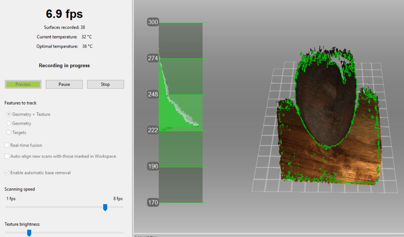
1. 3D SCANNING
Place artefact on wooden board for scanning, Scan one side (1st scan) then scan the opposite side (2nd scan).

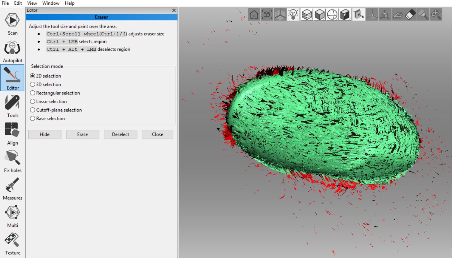
2. EDITING 3D SCANS
Erase the wooden base by selecting ‘BASE SELECTION’ (PRESS Ctrl + curser on a section you want to delete and wait for base to turn ‘red’) then press ERASE.
Select 2D to tidy up around the edges, press curser and move over section that needs deleting – enlarge the section by scrolling mouse.
Repeat on 2nd scan. SAVE each scan and make DUPLICATES

3. Go to TOOLS– run FINE REGISTRATION on each scan– press APPLY

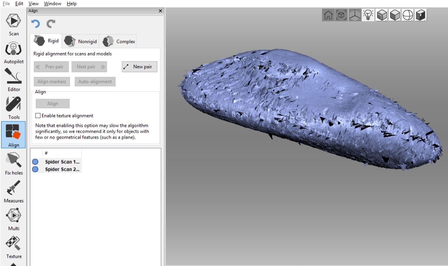
4. Go to ALIGN– select AUTOALIGN, if unsuccessful use NEW PAIR. To separate the scans in order to manipulate/move press SHIFT key + both sides mouse. Generally 8 points (4 each scan) are required. To move scan to align with second scan press SHIFT key and RIGHT mouse to manipulate and move one half of scan into place.


When scan is positioned and aligned with second scan click NEW PAIR and place a point on area of alignment (double clicking to set point), and place second point on other scan in the position that you think best aligns. Place points in several locations that match up and press ALIGN – APPLY – SAVE.
5. Go to TOOLS – Apply run GLOBAL REGISTRATION and press APPLY. Repeat similar with OUTLIER REMOVAL and SHARP FUSION – go to MESH SIMPLIFICATION reduce to 30 000 (make sure ‘Triangle Quantity’ is shown) press APPLY and SAVE project.


6. Go to TEXTURE – To add colour and texture to the 3D scan, go to MENU, select the 2 previous scans (and final aligned scan). Go to TEXTURE and here you can re-check the correct scans are shown (as shown in Left panel).


7. Make sure ‘export’ is ticked. Click APPLY.
8. Go to EDITOR – select POSITIONING TOOL – place 3 points on what you think is the base of the 3D scan and apply, you can also invert the image if not positioned properly on grid. SAVE project.
10. FILE – EXPORT MESHES – 3 new files (a ‘mtl’ , ‘obj’, ‘jpeg’ files) that will been created/saved in project folder. Make sure that “Save as type” at the bottom the Export Meshes dialog. is set to .obj to get your .obj, .jpg and .mtl. A new window will open ‘Model texture format’, make sure the JPEG option is chosen. Press export and this will save 3 files (a ‘mtl’, ‘obj’, ‘jpeg’ files) in the project folder.
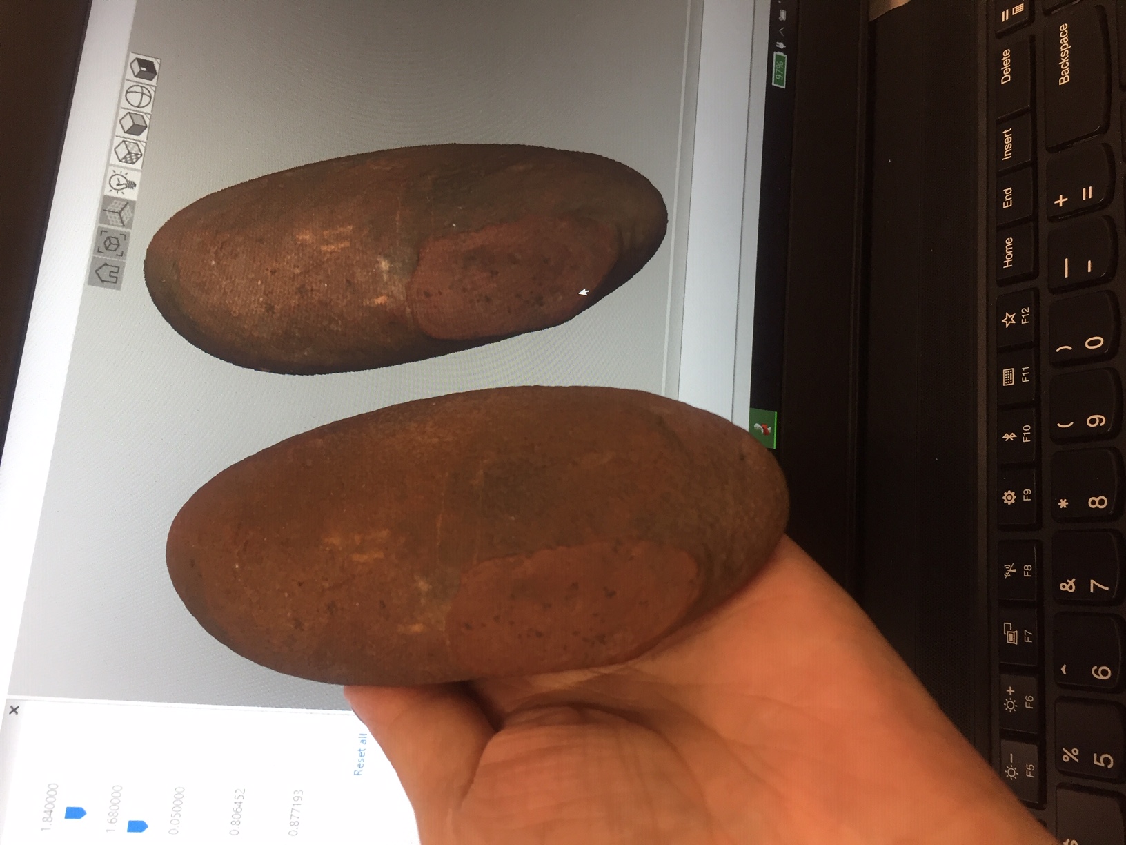
11. Open project folder on Desktop and create ‘Export’ folder cut-paste ‘mtl’ , ‘obj’, ‘jpeg’ files into this folder then these 3 files (3D scan) are ready to be uploaded to Recollect – Livinghistories@UON. This 3D artefact can be VIEWED HERE 

Also see the following on-line tutorials on 3D Scanning and Artec Studio Software.
Other on-line sources
3D Scanning with Artec Studio Software
Artec Studio 14 Basics – How to use Artec Studio 14 with the Artec Eva 3D Scanner
Industrial 3D Scanning Artec Space Spider
3D Scanning & Post-Processing – An Overview of Artec Studio Software
Small Tree Scanning with Artec3D
3D Scanning a Metal Part with Artec Space Spider
How to Manually Process 3D Scan Data Artec Studio 12 Software. Organic Objects
How to Manually Process 3D Scan Data in Artec Studio 12 Software. Mechanical Objects
Learn How to Scan Better, Faster and Smarter With the New Artec Studio 13 3D Scanning Software
Artec Studio 13: Great At Handling Large Scan Data Sets
Compiled by Ann Hardy ann.hardy@newcastle.edu.au or 49854594